Tri-Pole Shroud Design
This project was such a pleasure and a challenge to work on. In an area that had been classified as “sensitive” by our client, the initial request for this project was accuracy and realism.
As every wireless installation is different for the most part, the images rendered were based upon supplied drawings for a design already fabricated. In the process of hammering out the design, the request from the construction department was upscale a set of drawings (provided by our client) to meet the specifications of the proposed location and area.
Several factors considered for the upscale in design are primarily based on future network requirements.
This post will walk you through some of the major highlights of this build.
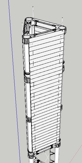
3D Tri-Pole Tower Rendering
Design Drawings & 3D Build
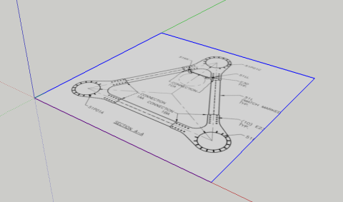
With the provided drawings we took the tower cross section and imported it into a 3D environment. Once imported the drawing was scaled up to the specifications provided by our clients construction department.
Design Drawings & 3D Build
(Provided drawing of tower cross section to be upscaled)
With the provided drawings we took the tower cross section and imported it into a 3D environment. Once imported the drawing was scaled up to the specifications provided by our clients construction department.
(Cross-section JPEG import into 3D environment)
At this point based on upscaled measurements, we started to draw and build out the the cross section and all of its details as well as the placement of the 3 poles and footings.
Like the construction of a real tower, the 3D model was build in segments and then assembled per the specifications provided.
As progress is made, test fitting of sections is done periodically to make sure that the components work properly. Once verified, drawing moved forward. As an added request, cross bracing was added between each elevation/section as shown below.
(Cross bracing and initial ladder fitting)
(Final ladder fitting and bracing)
(20m section of tower covered/shrouded to conceal antennas/transmission equipment)
(above) Full compound layout based on clients fence requirements. Prefabricated shelters added in from our 3D warehouse per each wireless carriers spec.
Now that the model is completed, geographic coordinates were added to the model so that lighting could be matched to the date and time the plate photography was taken onsite.
Final Rendering
Now that our model has been assigned coordinates and has been orientated per a provided land survey to its final resting place, we can now start the process of camera matching. This process takes the EXIF data from our onsite photos (inclusive of geographic coordinates) and assign them in to our real world 3D environment. Once created and assigned we can now start the process of final rendering per each view/location taken.
(Fully rendered tower section with sun light match. Tower textured in matte finishes to reduce reflective glare in final composite)
Final Matte Compositing
Final compositing for this project consisted of numerous images and views. Below we will focus on the compound and bottom section of the tower as it illustrates several key options that we can produce digitally for clients.
First we start off with a site image or “plate”. Unfortunately sometimes one cannot control the fact that a couple of backhoes were parked right in where our tower compound was to be located. Extra work was required to paint out the equipment.
After painting out the equipment the gravel driveway was painted in using other photographs taken onsite of various areas of the property
Now that we have a clean area our 3D tower and compound can be composited as layers once rendered out by software.
After viewing this final composite, the request to digitally landscape the image was brought up in discussion. Several days later, shooting reference photography, we digitally painted in cedar trees, a stone feature and painted in new grass on the berm in the foreground completing this one image.


